How does it work?
Implementation
1
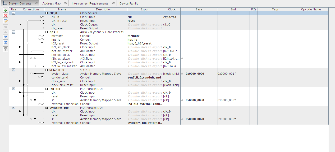
an HPS bridge was essential in order to assert the hardware on the board with the c program.
This was done using VHDL programs to map each pin signal on the board to an appropriate signal then exporting that as header files using the ‘qsys’ program on Quartus, this can be seen above as the initial setup.
2
Sample output on the Minicom terminal
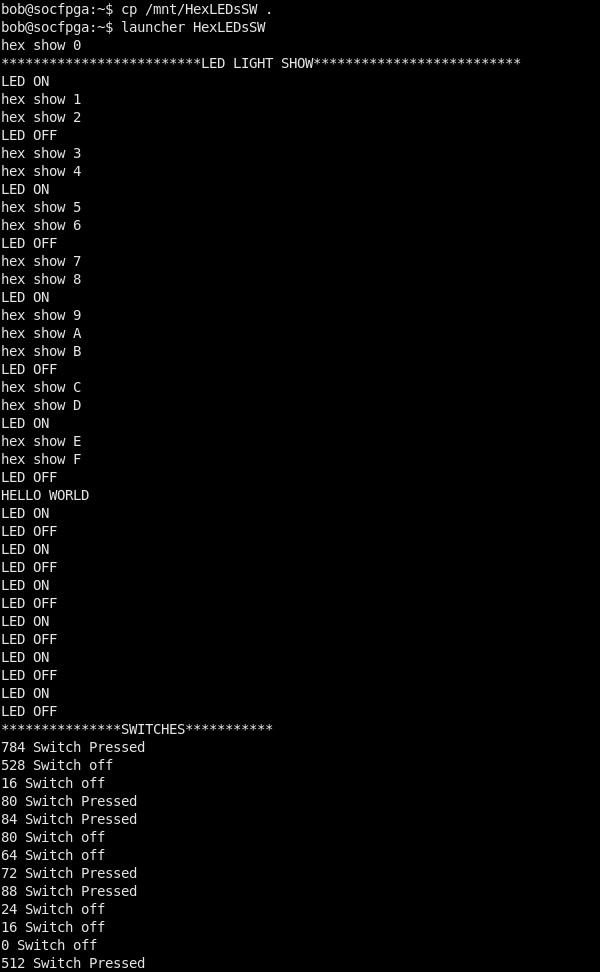
First a Light show occurs showing all hexadecimal digits on the LEDs and any switches that were turned on/off will also display on the terminal.
3
After the Light Show a message will be displayed on the 6 LEDS ("COE838"). We also print a message on the terminal "Hello World"
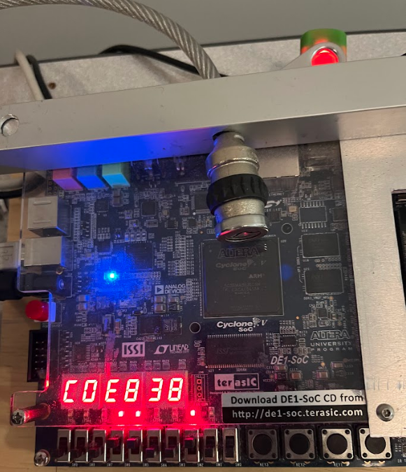
Any switches (bottom left 10 switches on the above image) pressed after that will be displayed on the terminal as "On/Off" and as a decimal representation of the 10 digit binary number
(ex. out of the 10 switches if 1 switch on the far left is pressed then that corresponding binary number is "1000000000" and in decimal that is 512).
